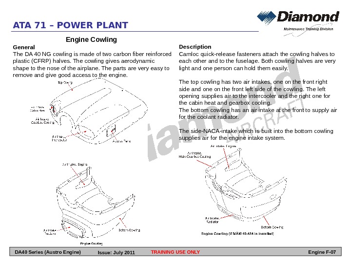

The doors are held in the open position by two hold open rods per fan cowl door. They can be opened during ground maintenance to give access to the components installed on the LP compressor case and to enable the thrust reverser halves (C - ducts) to be opened. There is also a deflection restraint on each fan cowl door that locates into the engine inlet cowl to prevent the fan cowl doors from twisting. Each door is attached to the aircraft pylon by four hinges and latched together by four latches at the bottom to close around the LP compressor case. The probe is located on the inner surface of the inlet cowl, right of the engine vertical centreline when viewed from the rear.įan Cowl Doors The fan cowl doors are manufactured from a lightweight composite material. Zone 1 Cooling The zone 1 cooling air inlet located at the top on the outer surface of the inlet cowl ducts ram air through the rear bulkhead to the area around the LP compressor case to provide cooling and ventilation for Zone 1 P20/T20 Probe The P20/T20 probe provides air inlet pressure and temperature to the EEC. There are two hoist attachment points on the left side and two equivalent points on the right side. This system supplies engine HP Compressor stage 3 air to the internal surface of the Air Intake Cowl inlet lip inner surface to prevent ice formation. The air is used to cool the electronic units and ventilate the electronic unit protection case. The air then flows back to the air intake cowl through a second tube to an exit hole located just below the NACA inlet. Įlectronic Unit Cooling When the engine is running, air flows through a NACA air inlet located on the left inner surface of the air intake cowl, then through a tube to the electronic unit protection box mounted on the fan case.
#Ata chapter 71 power plant manual#
Units to be installed in accordance with the Powerplant Build Up Manual The definition between the two options depends on whether certain items are installed these being: Opposite is a list of the items that require fitment to bring a Bare Engine upto QECU standard. When an engine is installed onto the wing it is defined as a Quick Engine Change Unit (QECU) and there are two main options available: A/ There are a number of combinations available using the components listed above. Pylon mounted, left and right hand thrust reverser halves (C - Ducts), (weight approx.Common nozzle assembly (CNA) (weight approx.Engine, associated fairings, front and rear mounts (weight approx.Right and left fan cowl doors (weight approx.Major Units The propulsion system comprises the following items:

Įvaluate the function and loads of the engine mounts.Identify the areas of the engine that supply the drain system.Describe the engine's pneumatic requirements for the aircraft.Itemise the units that form the Trent 700 nacelle.On completion of this section, you should be able to: SECTION 2 - PROPULSION SYSTEM (ATA Chapter 71 and Chapter 36)


 0 kommentar(er)
